The ZX81 is a great little machine, but it has only one video output option: an RF-modulator creating a signal suitable for (old) black-and-white TVs. This results in mediocre picture quality, and quite a limited set of suitable display devices.
To make matters even worse the ZX81's black-and-white signal lacks the "back porch", giving even many (modern) black-and-white TVs a hard time displaying a proper - meaning: still blurry - picture.
 |
| Picture from the ZX81's RF-modulator video output - usable, but not so good. |
A composite-video-output is pretty easy to build, improves picture quality, and allows the ZX81 to be connected to many more display devices, including color TVs and beamers.
A simple variant of the composite-video modification that is said to work with the 2nd edition ZX81 can be found at:
http://www.zx81.de/english/video_e.htm
 |
| Instructions/schematics from www.zx81.de as seen on 2022-01-25 |
The instructions from zx81.de look really feasible, and the ZX81 in question is a 2nd edition one, so I thought I'd try it.
I thought it would be a good idea to use pins and plugs as far as possible, for easy replacement of individual parts, if required, and put the components on a small extra circuit board, so I end up with some sort of "composite-video module". The ZX81 should be modified as little as possible.
For my composite-mod I used a C945 transistor and a 130 ohm resistor, a 3x1 pin header for the signals picked up from the ZX81, and a 2x1 pin header for the video output cable.
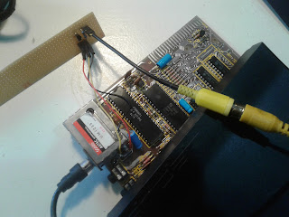 |
| Test run: Components soldered to circuit board, and wired up. RF-modulator connected for reference |
Three signals need to be picked up from the ZX81 to create a composite video signal: video from ULA pin 16, +5V, and GND. The RF-modulator box is easy to access for soldering, and provides all required signals.
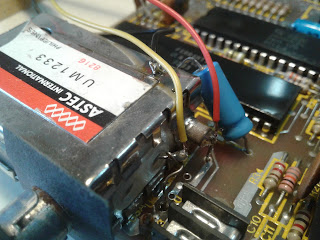 |
| Picking up signals from the RF-modulator box: video from ULA pin 16 is available on the left wire, +5V on the right, and the box's casing provides connection to GND |
Colored wires help keeping track what's going on - I used a yellow wire for video, red wire for +5V, and black wire for GND.
 |
| Ohyeah, that looks VERY good...! |
Switching everything on, and looking at the LCD TV's screen was quite a revelation. It looks as if the TV adds pixel smoothing, but the ZX81's pixels are too large to be detected, so only the edges get cleaned up. Or so.
Whatever - especially that inverse "L" looks laser-sharp!

The circuit board needed to be cut to fit inside the ZX81's case, and have some insulation. The new composite-video-output cable should go through the same opening in the ZX81's case as the RF-modulator jack.

One corner of the RF-modulator's shield plate was bent to make a little more room.

It turned out to be a bit tight, but looked like it'll work. So the ZX81 was reassembled and reconnected.
Now for a first "real-life" run let's put something meaningful on screen:
 |
| ZX81 reassembled, and printing some text to screen |
This LCD TV creates a near-perfect black-and-white picture from the ZX81's composite-video signal!
 |
| Close up of composite-video display on LCD TV |
There's a little horizontal jitter around the edges, but almost zero white or red or any bleeding from the pixels!
Wow, this is very good! It worked on first try, can easily be reverted, and the result is amazing!
I tried two more displays with the new composite-video output - the one shown in the pictures above was the best. One of the two others was a little blurry, and the other one had slight vertical stripes. Maybe a more sophisticated circuit will work better with these displays? Some more investigation and experimentation might improve the results further.
But for now, and for this setup, the "composite-video-output" modification for the ZX81 is a success, and huge improvement!
Special thanks to http://www.zx81.de/ for sharing their stuff!
* * *
DISCLAIMER: This is not an official instruction. Use at your own risk. No responsibility is taken.
No comments:
Post a Comment