Friday, January 28, 2022

The ZX81's character set

A table of the Sinclair ZX81's character set and codes is a essential tool for the ZX81 developer.


DEC.   HEX.   Character / [Description]

0      0x00     [SPACE]
1      0x01     [plot, top left]
2      0x02     [plot, top right]
3      0x03     [plot, top (both)]
4      0x04     [plot, bottom left]
5      0x05     [plot, left (both)]
6      0x06     [plot, bottom left and top right]
7      0x07     [plot, left (both) and top right]
8      0x08     [checkered]
9      0x09     [checkered, bottom]
10     0x0a     [checkered, top]
11     0x0b     "
12     0x0c     £
13     0x0d     $
14     0x0e     :
15     0x0f     ?

16     0x10     (
17     0x11     )
18     0x12     >
19     0x13     <
20     0x14     =
21     0x15     +
22     0x16     -
23     0x17     *
24     0x18     /
25     0x19     ;
26     0x1a     ,
27     0x1b     .
28     0x1c     0
29     0x1d     1
30     0x1e     2
31     0x1f     3

32     0x20     4
...
37     0x25     9
38     0x26     A
39     0x27     B
40     0x28     C
41     0x29     D
42     0x2a     E
43     0x2b     F
44     0x2c     G
45     0x2d     H
46     0x2e     I
47     0x2f      J
48     0x30     K
49     0x31     L
50     0x32     M
51     0x33     N
52     0x34     O
53     0x35     P
54     0x36     Q
55     0x37     R
56     0x38     S
57     0x39     T
58     0x3a     U
59     0x3b     V
60     0x3c     W
61     0x3d     X
62     0x3e     Y
63     0x3f     Z

64     0x40     RND
65     0x41     INKEY$
66     0x42     PI

67     0x43     to
111     0x6f     non-printable/unused

112     0x70     UP
113     0x71     DOWN
114     0x72     LEFT
115     0x73     RIGHT
116     0x74     GRAPHICS
117     0x75     EDIT
118     0x76     NEWLINE
119     0x77     RUBOUT
120     0x78     K/L MODE
121     0x79     FUNCTION
122     0x7a to
125     0x7d     non-printable/unused
126     0x7e     NUMBER
127     0x7f      CURSOR

128     0x80 to
191     0xbf       inverse of 0x00 to 0x3f

192     0xc0     "" [double-quotes]
193     0xc1     AT
194     0xc2     TAB
195     0xc3     non-printable/unused
196     0xc4     CODE
197     0xc5     VAL
198     0xc6     LEN
199     0xc7     SIN
200     0xc8     COS
201     0xc9     TAN
202     0xca     ASN
203     0xcb     ACS
204     0xcc     ATN
205     0xcd     LN
206     0xce     EXP
207     0xcf     INT

208     0xd0     SQR
209     0xd1     SGN
210     0xd2     ABS
211     0xd3     PEEK
212     0xd4     USR
213     0xd5     STR$
214     0xd6     CHR$
215     0xd7     NOT
216     0xd8     ** (double asterisk)
217     0xd9     OR
218     0xda     AND
219     0xdb     <=
220     0xdc     >=
221     0xdd     <>
222     0xde     THEN
223     0xdf     TO

224     0xe0     STEP
225     0xe1     LPRINT
226     0xe2     LLIST
227     0xe3     STOP
228     0xe4     SLOW
229     0xe5     FAST
230     0xe6     NEW
231     0xe7     SCROLL
232     0xe8     CONT
233     0xe9     DIM
234     0xea     REM
235     0xeb     FOR
236     0xec     GOTO
237     0xed     GOSUB
238     0xee     INPUT
239     0xef     LOAD

240     0xf0   LIST
241     0xf1   LET
242     0xf2    PAUSE
243     0xf3     NEXT
244     0xf4    POKE
245     0xf5   PRINT
246     0xf6    PLOT
247     0xf7    RUN
248     0xf8    SAVE
249     0xf9    RAND
250     0xfa    IF
251     0xfb    CLS
252     0xfc     UNPLOT
253     0xfd     CLEAR
254     0xfe     RETURN
255     0xff     COPY

Wednesday, January 26, 2022

Composite-video-out modification with circuit board

The ZX81 is a great little machine, but it has only one video output option: an RF-modulator creating a signal suitable for (old) black-and-white TVs. This results in mediocre picture quality, and quite a limited set of suitable display devices.

To make matters even worse the ZX81's black-and-white signal lacks the "back porch", giving even many (modern) black-and-white TVs a hard time displaying a proper - meaning: still blurry - picture.

Picture from the ZX81's RF-modulator video output - usable, but not so good.

A composite-video-output is pretty easy to build, improves picture quality, and allows the ZX81 to be connected to many more display devices, including color TVs and beamers.

A simple variant of the composite-video modification that is said to work with the 2nd edition ZX81 can be found at:

http://www.zx81.de/english/video_e.htm

Instructions/schematics from www.zx81.de as seen on 2022-01-25

The instructions from zx81.de look really feasible, and the ZX81 in question is a 2nd edition one, so I thought I'd try it.

I thought it would be a good idea to use pins and plugs as far as possible, for easy replacement of individual parts, if required, and put the components on a small extra circuit board, so I end up with some sort of "composite-video module". The ZX81 should be modified as little as possible.

For my composite-mod I used a C945 transistor and a 130 ohm resistor, a 3x1 pin header for the signals picked up from the ZX81, and a 2x1 pin header for the video output cable.

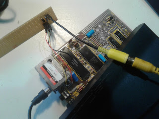
Test run: Components soldered to circuit board, and wired up. RF-modulator connected for reference

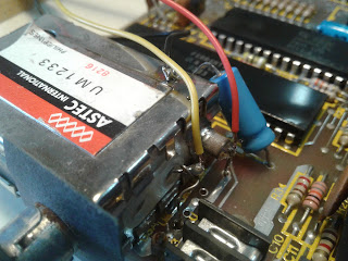
Three signals need to be picked up from the ZX81 to create a composite video signal: video from ULA pin 16, +5V, and GND. The RF-modulator box is easy to access for soldering, and provides all required signals.

Picking up signals from the RF-modulator box: video from ULA pin 16 is available on the left wire, +5V on the right, and the box's casing provides connection to GND

Colored wires help keeping track what's going on - I used a yellow wire for video, red wire for +5V, and black wire for GND. 

Ohyeah, that looks VERY good...!

Switching everything on, and looking at the LCD TV's screen was quite a revelation. It looks as if the TV adds pixel smoothing, but the ZX81's pixels are too large to be detected, so only the edges get cleaned up. Or so.

Whatever - especially that inverse "L" looks laser-sharp!

The circuit board needed to be cut to fit inside the ZX81's case, and have some insulation. The new composite-video-output cable should go through the same opening in the ZX81's case as the RF-modulator jack.

One corner of the RF-modulator's shield plate was bent to make a little more room.

It turned out to be a bit tight, but looked like it'll work. So the ZX81 was reassembled and reconnected.

Now for a first "real-life" run let's put something meaningful on screen: 

ZX81 reassembled, and printing some text to screen

This LCD TV creates a near-perfect black-and-white picture from the ZX81's composite-video signal!

Close up of composite-video display on LCD TV

There's a little horizontal jitter around the edges, but almost zero white or red or any bleeding from the pixels!

Wow, this is very good! It worked on first try, can easily be reverted, and the result is amazing!

I tried two more displays with the new composite-video output - the one shown in the pictures above was the best. One of the two others was a little blurry, and the other one had slight vertical stripes. Maybe a more sophisticated circuit will work better with these displays? Some more investigation and experimentation might improve the results further.

But for now, and for this setup, the "composite-video-output" modification for the ZX81 is a success, and huge improvement!

Special thanks to http://www.zx81.de/ for sharing their stuff! 

* * *

DISCLAIMER: This is not an official instruction. Use at your own risk. No responsibility is taken.

ZX81... alive!